What is ESP32?
Hi,
In this regard, we will introduce you to what ESP32 is.
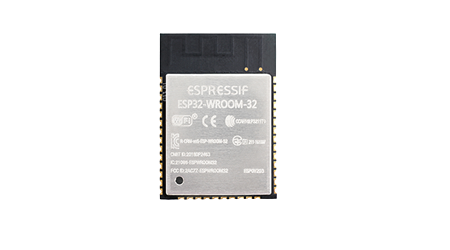
ESP32 is a feature-rich microcontroller with integrated Wi-Fi and Bluetooth connectivity for a wide variety of applications, as the manufacturer ESPRESSIF writes on its page.
Thanks to the Wi-Fi and Bluetooth on the ESP32, it has a useful structure for many IOT applications. ESP32 modules, which have a modular structure on the chip, as in ESP8266, make it very easy to design your own PCB board. In addition, thanks to its low power consumption feature in sleep mode, it is also suitable for applications with low power consumption.
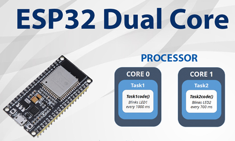
The ESP32 WROOM and WROVER variants have two cores, named “Core 0” and “Core 1”. It is possible to determine which core will do which job with a few simple operations. Although this is similar to the concept of “multi threading”, it is actually a more beneficial situation with the feature that both processes can take place at the same time. As an example, a Web Server and Stepper Motor drive operations that you will create with ESP32 can be performed at the same time without interruption. If you use the Arduino IDE directly without making a selection, the ESP32 will perform the operations on “Core 1”. You can look at the internet for details on the core selection process, which I will not mention on this subject.
The ESP32 has an adjustable clock speed between 80 and 240 MHz. This setting can be done while loading the software on the Arduino IDE. You can make the selection process according to your needs. In applications that require high performance, 240Mhz can be selected, but in applications where less power consumption is desired, 80Mhz can be selected. In addition, its internal memory can go up to 16Mb in some models, which is very useful in large software.
GPIO
Now let’s take a look at the GPIOs of the ESP32. I recommend the site in the link for many topics about using ESP32 with Arduino. It is a useful page in my opinion, as it is explained with full content and supported by pictures. The content in this topic also contains excerpts from that site. Let’s start with the pin reference of the ESP32 module.
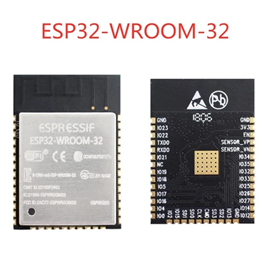
As you can see in the picture, there are many pins on the ESP32. However, it is not possible to use all of these pins directly as GPIO. It is strictly not recommended to use the pins between GPIO9 and GPIO11 for any operation. Because these pins are connected to the flash memory of the ESP32. In addition, it can only use pins between GPIO34 and GPIO39 as inputs. Unfortunately, it is not possible to use it as an output. In addition, some pins have different initial behavior. For example, keeping the GPIO12 pin in the HIGH position while powering the ESP32 prevents the ESP32 from working. It is not possible to change them because these are the features originating from the structure of ESP32. For this reason, it is important to examine the GPIO table on the page in the link in the systems you will design in order to minimize the errors that may occur.
PERIPHERALS
Arduino is available on ESP32 in hardware such as ADC, SPI, I2C or DAC that we are used to. However, in addition to these, there are internal capacitive “Touch” pins and “Hall Efect” sensor on the ESP32. While the Hall effect sensor can measure the changes in the magnetic field, the Touch pins enable the metal surface that you connect via cable to turn into a touch sensor. In other words, the value you read from the pin provides different values when you touch the metal surface and different values when you do not touch it.
The ADC and PWM used in ESP32 contain a little more detail than the use in Arduino. While it is possible to use the ADC simply without additional settings, additional settings are required to use PWM. Because when using PWM, the frequency, channel and the pin where the channel will be used must be set manually. In fact, although this seems like a disadvantage, PWM feature can be given to all pins on the ESP32. The ADC used in ESP32 can be used up to 12 bits.
As in PWM, all pins on the ESP32 can be used for I2C communication. However, when using the Arduino IDE, GPIO21 and GPIO22 are set as default I2C pins. If you want to change, it is enough to give the pins you want to use as a parameter to the “Wire.begin()” function. Of course, the pin you will use should not have any of the restrictions given in the ESP32 GPIO table. In other words, since GPIO36 is only an input, using it as I2C may cause problems.
In addition to these, ESP32 has 4 SPIs and 1 2-channel DAC. Only 2 of the SPIs are available for use. These are called VSPI and HSPI. I couldn’t see any difference between them. They are just named differently as nomenclature. Other SPIs are used for flash memory.
In my opinion, the biggest disadvantage of ESP32 is that when Wi-Fi is activated, some hardware on the ESP32 becomes unusable. It is not possible to use ADC2 while Wi-Fi is active. The second biggest drawback is that many ESP32 modules are not breadboard compatible. For this reason, it is a little difficult to use. Also, remember that when using ESP32, the pins can give a maximum current of 40mA.